VMware Workstation and GNS3 are two platforms which are very handy to test and evaluate solutions before live implementation. By default each of those platforms is separate, however both have components which allow integration. What that means is that it is possible to have virtual machines hosted on VMware Workstation to communicate with Cisco equipment which is running oin GNS3.
By default VMware Workstation has 10 virtual networks which are named VMnet0, VMnet1, … , VMnet9. Each of those networks can be used as:
- Bridged – virtual network connected seamless way to physical adapter. Virtual machines connected to bridged network will appear in same network as physical adapter connected to computer.
- NAT – VMware will translate virtual network and computers connected to that network and allow communication acting as gateway
- Host-only – network available only for virtual machines connected to it. private network for virtual machines.
Configuration of virtual networks is flexible and can be adjusted easily. Each of virtual networks can be also presented on host computer as network adapter.
In GNS3 environment we have Cloud Node Type which can be configured to communicate with any network adapter installed on the computer on which GNS3 is running
So, if we connect those two facts together:
- virtual network on VMware Workstation can be presented as network adapter on host computer
- Cloud Node Type on GNS3 can connect to any network adapter installed on host computer
it is possible to integrate both environments together to expand our testing LAB.

VMware Workstation 8 Configuration
Let’s start from Vmware workstation preparation. For demonstration purposes I will use VMware wosktation 8. So, first step is to go to Edit menu and then Virtual network Editor. You should see screen similar to the one below:
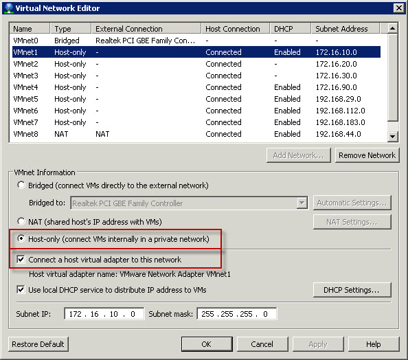
Click on VMnet1 and indicate following options in Vmnet Information section below list of the virtual networks:
- Host-only (connect VMs internally in a private network) – limit traffic only to computer on which we have VMware and GNS3 installed
- Connect a host virtual adapter to this network – that will create network adapter on host computer
- Optional is Use local DHCP service to distribute IP addresses to VMs. I would recommend to enable DHCP as that way VMware will handle dynamic address assignment to devices/systems which will require that
Once all parameters are set click OK to confirm settings for VMnet1.
NOTE
For demonstration purposes I did use VMnet1, so I will refer to VMnet1 in this article. If you want to configure different VMnet, that’s fine. Just keep in mind that you have to refer to your VMnet in all places where VMnet1 is mentioned.
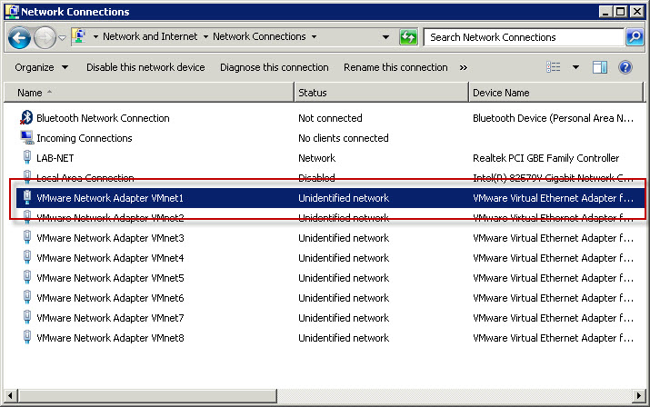
Once VMnet1 configuration is completed new network adapter should appear in Network Connections in Windows. VMware will automatically name that network connection VMware Network Adapter VMnet1.
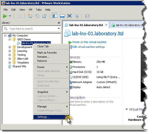
Next step is to assign VMnet1 virtual network to Network Adapter in test machine. As test machine, to demonstrate how communication between VMware workstation and CNG3 will work, I will use Debian 6. So, right-click on machine which you want to communicate with GNS3 environment and then click Settings from context menu.
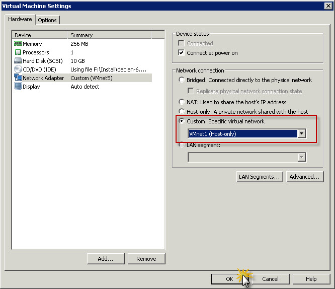
Then on the list of components highlight Network Adapter and in Network connection section click Custom and from drop-down list pickup VMnet1 (Host-only).
After that start virtual machine. In my case, once virtual machine was up and running I just logged in as root to check IP address and it has been assigned by VMware DHCP.
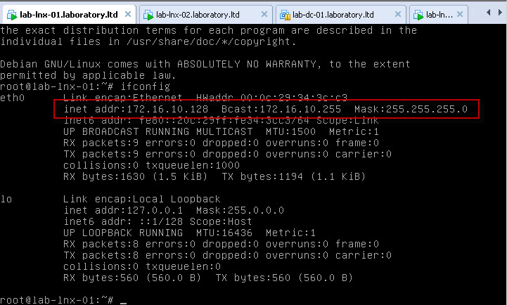
Now, once VMware Workstation part of configuration is ready we can move on and try to configure GNS3 to talk to VMnet1 and Debian 6 connected to VMnet1 virtual network.
GNS3 configuration
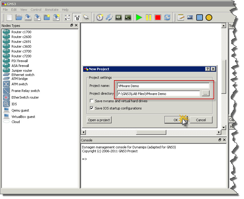
First thing is to start GNS3 🙂 and create new project. I named project VMware Demo. Then click OK and GNS3 will create new project with blank topology.
Now just drag and drop Router object to topology area (assumption is that GNS3 is properly configured with IOS images, so you can add routers to topology and run them). Once router is there drag and drop Cloud object as well and then right-click on Cloud object and chose Configuration from context menu.
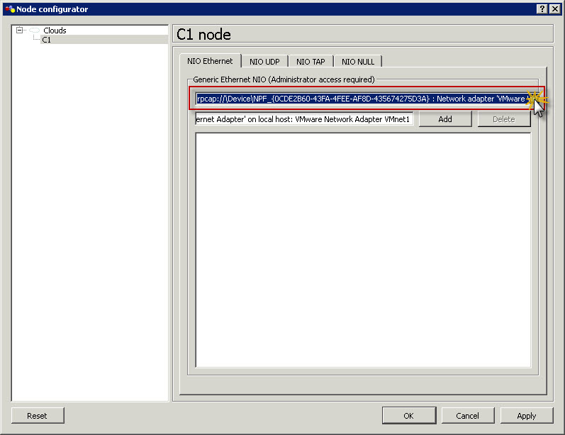
In Node configuration window for cloud click on C1 node on the list. Then on NIO Ethernet tab click on drop-down list with all adapters and locate VMnet1 adapter and then highlight it.
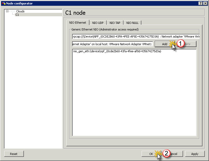
Once VMnet1 is highlighted in drop-down list click Add button to add this adapter to active adapters for Cloud node and then click OK.
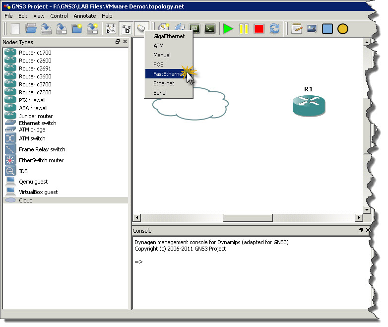
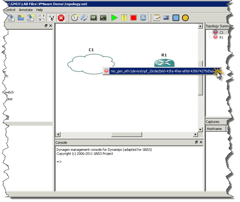
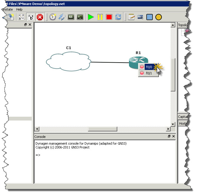
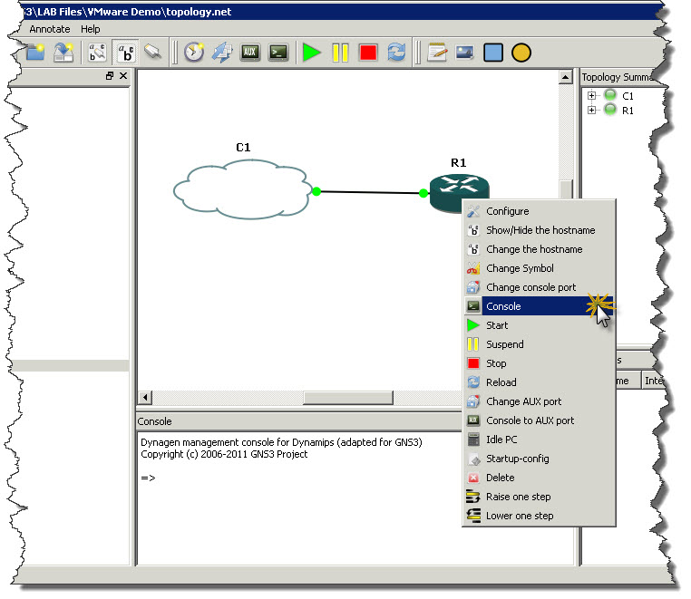
After that it’s easy. Click Add link button on toolbar and choose FastEthernet a type of connection we want to make. Then click on Cloud to see list of interfaces you can use for FastEthernet connectivity. There should be only one interface which represents out VMnet1 network. Click on that interface and them move mouse over R1 router and click on it. From list of interfaces on the router click the one you want to connect to Cloud (in my example I’m using FastEthernet0/0 on R1 to connect router with cloud). Screenshots below showing whole process of creating link between cloud and router.
Once router is connect with cloud you can start router (green play button) and then right-click on the router and open router’s console.
In next section GNS3 Console you can see configuration of the router. Highlited lines on the listing below show where interaction or command is required. There is plenty of system information from boot process of the router to show whole process as much accurate as possible.
GNS3 Console
Connected to Dynamips VM "R1" (ID 0, type c3600) - Console port
Press ENTER to get the prompt.
################################################################################
############################################################################# [OK]

Smart Init is disabled. IOMEM set to: 5

Using iomem percentage: 5

Restricted Rights Legend

Use, duplication, or disclosure by the Government is
subject to restrictions as set forth in subparagraph
(c) of the Commercial Computer Software - Restricted
Rights clause at FAR sec. 52.227-19 and subparagraph
(c) (1) (ii) of the Rights in Technical Data and Computer
Software clause at DFARS sec. 252.227-7013.

cisco Systems, Inc.
170 West Tasman Drive
San Jose, California 95134-1706

Cisco IOS Software, 3600 Software (C3660-A3JK9S-M), Version 12.4(25c), RELEASE SOFTWARE (fc2)
Technical Support: http://www.cisco.com/techsupport
Copyright (c) 1986-2010 by Cisco Systems, Inc.
Compiled Fri 12-Feb-10 01:23 by prod_rel_team

This product contains cryptographic features and is subject to United
States and local country laws governing import, export, transfer and
use. Delivery of Cisco cryptographic products does not imply
third-party authority to import, export, distribute or use encryption.
Importers, exporters, distributors and users are responsible for
compliance with U.S. and local country laws. By using this product you
agree to comply with applicable laws and regulations. If you are unable
to comply with U.S. and local laws, return this product immediately.

A summary of U.S. laws governing Cisco cryptographic products may be found at:
http://www.cisco.com/wwl/export/crypto/tool/stqrg.html

If you require further assistance please contact us by sending email to
export@cisco.com

Cisco 3660 (R527x) processor (revision 1.0) with 124928K/6144K bytes of memory.
Processor board ID FTX0945W0MY
R527x CPU at 250MHz, Implementation 40, Rev 1.2, 512KB L2 Cache

3660 Chassis type: ENTERPRISE
2 FastEthernet interfaces
DRAM configuration is 64 bits wide with parity enabled.
125K bytes of NVRAM.
8192K bytes of processor board System flash (Read/Write)

--- System Configuration Dialog ---

Would you like to enter the initial configuration dialog? [yes/no]: no

Press RETURN to get started!

*Mar  1 00:00:03.439: %LINEPROTO-5-UPDOWN: Line protocol on Interface VoIP-Null0, changed state to up
*Mar  1 00:00:03.691: %LINEPROTO-5-UPDOWN: Line protocol on Interface IPv6-mpls, changed state to up
*Mar  1 00:00:04.079: %LINK-3-UPDOWN: Interface FastEthernet0/0, changed state to up
*Mar  1 00:00:04.127: %LINK-3-UPDOWN: Interface FastEthernet0/1, changed state to up
*Mar  1 00:00:05.079: %LINEPROTO-5-UPDOWN: Line protocol on Interface FastEthernet0/0, changed state to up
*Mar  1 00:00:05.127: %LINEPROTO-5-UPDOWN: Line protocol on Interface FastEthernet0/1, changed state to up
*Mar  1 00:00:12.491: AUTOINSTALL: FastEthernet0/0 is assigned 172.16.10.129
*Mar  1 00:00:12.495: AUTOINSTALL: Obtain siaddr 172.16.10.254 (as config server)
*Mar  1 00:01:13.439: %IP-5-WEBINST_KILL: Terminating DNS process
*Mar  1 00:01:14.051: %LINK-5-CHANGED: Interface FastEthernet0/1, changed state to administratively down
*Mar  1 00:01:15.051: %LINEPROTO-5-UPDOWN: Line protocol on Interface FastEthernet0/1, changed state to down
*Mar  1 00:01:19.655: %SYS-5-RESTART: System restarted --
Cisco IOS Software, 3600 Software (C3660-A3JK9S-M), Version 12.4(25c), RELEASE SOFTWARE (fc2)
Technical Support: http://www.cisco.com/techsupport
Copyright (c) 1986-2010 by Cisco Systems, Inc.
Compiled Fri 12-Feb-10 01:23 by prod_rel_team
*Mar  1 00:01:19.659: %SNMP-5-COLDSTART: SNMP agent on host Router is undergoing a cold start
Router>ena
Router#conf t
Enter configuration commands, one per line.  End with CNTL/Z.
Router(config)#int fa0/0
Router(config-if)#no shut
Router(config-if)#ip address 172.16.10.11 255.255.255.0
Router(config-if)#exit
Router(config)#exit
Router#ping 172.16.10.128

Type escape sequence to abort.
Sending 5, 100-byte ICMP Echos to 172.16.10.128, timeout is 2 seconds:
.!!!!
Success rate is 80 percent (4/5), round-trip min/avg/max = 4/9/16 ms
Router#
R1 configuration
Router#sh run
Building configuration...

Current configuration : 605 bytes
!
version 12.4
service timestamps debug datetime msec
service timestamps log datetime msec
no service password-encryption
!
hostname Router
!
boot-start-marker
boot-end-marker
!
no aaa new-model
memory-size iomem 5
!
ip cef
!
interface FastEthernet0/0
ip address 172.16.10.11 255.255.255.0
duplex auto
speed auto
!
interface FastEthernet0/1
no ip address
shutdown
duplex auto
speed auto
!
ip http server
no ip http secure-server
ip forward-protocol nd
!
control-plane
!
line con 0
line aux 0
line vty 0 4
login
!
end

Router#
Test connectivity from virtual machine with Debian 6
Now we can try to ping router (IP 172.16.10.11) from vitual machine. Once we see success it means that VMware can talk to GNS3 and vice versa.
Done !!! 🙂
Now VMware Workstation 8 is integrated with GNS3 which gives much more opportunities for testing and evaluating potential solutions.




Good post, detailed for anybody new to gns3.
Thanks,
Sachin
Hi any body tell me that i can not this on windows 7 or not
Thanks
akhilesh
Hi Akhilesh,
you can do this on Windows 7. All screenshots in this article are taken on Windows 7 Ultimate 64-bit machine, so this all works on Windows 7 with no problems.
Thanks,
Szymon
Hi,
Thanks for the post it was great.
i have one question.
How to implement vlan settings in nested virtualization in GNS3.
Using switches/routers.
Nested virtualization= when i install ESX in virtual machine and then install vm on/inside these Esx machine and they are using port groups for communication.
Thanks in Advance.
I guess easiest option would be to create multiple virtual networks and assign each network to different vlan and have multiple virtual networks assigned to machines.
SKufel
For the life of my I can not get this to work.. I can only ping the local VMnet1 interface created on my host computer. I used 192.168.2.0 as my subnet. I can ping 192.168.2.1 from my router within GNS3 but I can not ping the VMware guest at 192.168.2.128. If anyone can assist I would be very thankful!
Nice post.
I have a doubt, if I install GNS3 on the physical machine can i integrate with VM machine?
Yes, you can. Post shows how to do that. However, GNS3 and VMware are on the same machine.
If you have both on separate computers then you can communicate through LAN, but GNS3 will not be able to connect directly to VMnet adapters.
This post was really helpful for me today.
I am very grateful.
Please, in this case it is the VMware’s DHCP Server that was used.
How do I configure to use the Router’s DHCP Server?
Once you configure GNS3 to communicate with VMnet you can just configure DHCP on router and use it. Prior to that you can disable DHCP on VMware Workstation side by changing options of particular VMnet in VIrtual Network Manager.
If you looking for information how to configure DHCP on router/switch, here is quick config snippet:
https://blog.skufel.net/2011/11/config-snippets-cisco-dhcp-on-catalyst-switches/
I get all the way to the step below, and my issue is that when I click the drop down list, all of the vmware nics do not show up. I only have the origionals vmware1 and 8. I have confirmed that these exsist with the assigned IP addresses in Windows and by viewing the ifconfig settings in the actual vm. I also attempted reinstalling gns3 because those vmnic’s were created after the origional installation thinking that might be the issue; needless to say it did not help. They still dont show up in the list. Any direction would be appreciated.
Node configuration window for cloud click on C1 node on the list. Then on NIO Ethernet tab click on drop-down list with all adapters and locate VMnet1 adapter and then highlight it.
Do you run GNS3 on the account with local admin privileges?
Sometimes this does block access to network interface information.
HI
thinks for this post but i have one question please i have an architecture network and in the virual machine i have the monotoring outils opennms how i can make my presentation if you have the answer i’m so greatful think you
What you mean by making presentation?
Can you elaborate a little bit more what exactly you want to achieve?
Hi SKufel! I just found this well written guide. I know how to do all of this, but I have another question: I have two VMs in VMware connected to the same VMnet (let’s say VMnet8), because I want them both to be on the same subnet. Is there a way to add them separately into GNS3? Because if I connect a cloud to VMnet8, then technically this cloud has both the VMs in it. Also, I can’t add two clouds and connect both clouds to VMnet8 because that will just be duplicating them. I want to add them into GNS3 separately because I want to connect each VM to a separate port to the switch in GNS3, because I want to configure SPAN (port mirroring). Any ideas?
hello
I want to make a simulation of network monitoring tool using opennms
So the virtual machine I installed opennms and I made a archtecture on gns3 so I tested the connection and all is well then I can do is managing network devices that are on gns3
The only way I’ve found to work so far is to add a separate adapter. So one cloud has VMnet8 and another has say VMnet7. This works well, but the issue is that there are only so many VMnets. Does anyone have a way to connect multiple VMs in GNS3 with only one adapter?
Thanks, this really helps.
Restart the NetGroup Packet Filter Driver service.
http://rtomaszewski.blogspot.co.uk/2012/10/gns3-doesnt-list-new-virtualbox-network.html
This document was quite helpful.. I have just started using GNS and this helped me bring my VM workstation images into a cloud as shown so i can use my own Vms for the hosts…
learning to add the routers in correctly is not simple, and can be a little problematic. i had to remove gns3 completely, reinstall and start over again and thsi time, i have all the router types C types, and virtual box and vm workstation images all working..
thanks for the writeup!
It seems like u really understand quite a lot regarding this
subject matter and it all demonstrates throughout this posting,
titled “How-to : VMware Workstation 8 and GNS3 integration | SK Tech Scratchpad”.
Thank you ,Faustino
Thanku
Thanks a lot my friend this is really an awesome note.
Hello Mate,
Thanks for this very helpful post.
Much appreciated!
Cheers!
Hi,
I would like to know how I can connect all vmnet2 to vmnet7 to gns3?
example:
vmnet1= GNS3 = 192.168.10.0/24
vmnet2= WinXP= 192.168.20.0/24
vmnet3= WinXP= 192.168.30.0/24
vmnet1 will have 2 L3 IOU switches connecting to vmnet2 and vmnet3 respectively
end result is that vmnet2 and vmnet3 should be able to ping each other …
In GNS3 you can add as many network adapters as you have. So, all vmnetX networks can be connected to one cloud object.
Then you can connect different ports on router or switch to selected ports on cloud object.
hi Skufel,
I can add three VMnet in GNS3 1.2.1 version. but I need to add at least 5 or 6 VMnet with GNS3. I tried it into two different laptop but in both laptop it can connect max three VMnet with GNS3.
any solution please
I just re-checked to make sure and was able to add 6 VMnet adapters to one cloud object in GNS3 1.2.1. I think that you have to look into VMware / Edit / Virtual Network Editor and define all VMnet adapters there.
Once it’s done you should see all VMnet adapters in GNS3. I’d say it’s default VMware installation which creates maximum of 3 VMnet adapters by default. More has to be added manually.
Hope that helps.
I have installed GNS3 and VMWare Work Station 9 and have som eissue with CPU utilization getting hammered. resting at 50% when Routers and switches are Idle. Do you know or have you run into a fix for this?
Thanks
This is common thing with GNS3. What you have to do is to find proper idle value for Cisco IOS images which you are using with your GNS3. When you right-click on router icon in GNS3 you will see option called Idle-PC.
Try to find optimal value using that option. When idle value counted for your system by GNS3 will be optimal then processor utilization will go down nearly to 0% when routers will be idle.
i should say this article helped me my whole day problem. i spent hours looking for wat i found one this single page
5 stars!!
That was wonderful. Thanks a lot SKufel 😉
Fantastic site. Lots of useful information here. I’m
sending it to several pals ans also sharing in delicious.
And of course, thank you to your sweat!